2009-07-30

Draw rounded rectangles with GdiPlusX

Bob Powell, in his great website site says: "the trick here is to use a GraphicsPath object to assemble a collection of  lines and arcs that make up the rounded rectangle shape.

Arcs are used to round off the corners, so you have to position the lines 1 radius, whatever that may be, from the actual corner."


The code below shows Bob's function converted to VFP and GdiPlusX, to obtain this result:


LOCAL loBmp AS xfcBitmap, loGfx AS xfcGraphics
WITH _SCREEN.SYSTEM.Drawing AS xfcDrawing
 * create a New Bitmap
 loBmp = .Bitmap.New(200,170)
 * get a Graphics object for Drawing
 loGfx = .Graphics.fromImage(loBmp)
 * clear the Drawing canvas
 loGfx.CLEAR(.COLOR.LightCoral)
 * Draw the rounded rectangle
 =DrawRoundRect(loGfx, .Pens.blue, 20, 30, 150, 100, 20)
 * save image to file
 loBmp.SAVE("roundedrect.png", .Imaging.ImageFormat.Png)
ENDWITH
RUN /N explorer.EXE RoundedRect.png


FUNCTION DrawRoundRect(toGfx AS xfcGraphics, toPen AS xfcPen, ;
  tnX, tnY, tnWidth, tnHeight, tnRadius)
 * adapted by cesar from bob powell's sample taken from
 * http://www.bobpowell.net/roundrects.htm

 LOCAL logPath AS xfcGraphicsPath
 logPath = _SCREEN.SYSTEM.Drawing.Drawing2d.GraphicsPath.New()

 WITH logPath
  .AddLine(tnX + tnRadius, tnY, tnX + tnWidth - (tnRadius*2), tnY)
  .AddArc(tnX + tnWidth - (tnRadius*2), tnY, tnRadius*2, tnRadius*2, 270, 90)
  .AddLine(tnX + tnWidth, tnY + tnRadius, tnX + tnWidth, tnY + tnHeight - (tnRadius*2))
  .AddArc(tnX + tnWidth - (tnRadius*2), tnY + tnHeight - (tnRadius*2), tnRadius*2, tnRadius*2,0,90)
  .AddLine(tnX + tnWidth - (tnRadius*2), tnY + tnHeight, tnX + tnRadius, tnY + tnHeight)
  .AddArc(tnX, tnY + tnHeight - (tnRadius*2), tnRadius*2, tnRadius*2, 90, 90)
  .AddLine(tnX, tnY + tnHeight - (tnRadius*2), tnX, tnY + tnRadius)
  .AddArc(tnX, tnY, tnRadius*2, tnRadius*2, 180, 90)
  .closefigure()
 ENDWITH
 toGfx.DrawPath(toPen, logPath)
ENDFUNC


The above function receives a xfcPen object to draw the rounded rectangle. In order to draw a filled rounded rectangle, all we need is to add a small tweak in the above function to use a brush object instead a pen, and call the FillPath function instead of DrawPath.

2009-07-06

Drawing shapes using the PolyPoints property

vfp9 brought a new property that allows us to draw all kinds of shapes, without the need of any external component, even a single windoes api call.


according to the vfp9 help, the polypoints property of the shape control "specifies an array of coordinates for creating polygon shapes using the shape control and polygon lines using the line control. read/write at design time and run time. for shape controls, polypoints creates a polygon shape."


mvp luis maria guayan from argentina already did an amazing job using the polypoints property, in 2 articles.


dibujando polígonos con vfp 9.0 - a simple article with some samples showing how we can draw a traiangle and an ogtogon. the article is in spanish, but it is very simple to run the provided samples and reproduce the proposed result.


the 2nd one, gráficas con objetos 100% vfp, is a real masterpiece, where he uses the polypoints property to create chart shapes, providing a very nice charting tool. download the source code and play with the samples, amazing !


using the polypoints property we can also draw rounded shapes, pie slices, circles and ellipses.


create an empty form, size it the way you like, and paste the following code to the init() event, to reproduce the shape below:


thisform.addobject("shape1", "shape")
* add a shape object to the current form
* and set some basic properties
local loshape
as shape
loshape = thisform
.shape1
loshape.
width = thisform.
width
loshape.height = thisform.
height
loshape.anchor = 15
&& resize width and height
loshape.backcolor = rgb
(255,0,0)
loshape.
polypoints = "apoly"
&& array of points
loshape.visible
= .t.
 
* defining the polypoints array
* change the values of lnstart and lnfinal to determine
* the angle of the pie slice
local
lnstart, lnfinal, lnsweep, n, lnradius, lnangle
lnstart = 0
lnfinal = 360

lnsweep = lnfinal - lnstart
lnradius = 50


public apoly(lnsweep + 2, 2)
for n = 1 to
lnsweep + 1
   lnangle = lnstart + n - 1
   apoly(n,1) = (lnradius *
cos(dtor
(lnangle)) + lnradius)
   apoly(n,2) = (lnradius *
sin(dtor
(lnangle)) + lnradius)
endfor


if lnsweep = 360 && closed ellipse, so dont draw the center point
   apoly(n,1) = apoly(n-1,1)
   apoly(n,2) = apoly(n-1,2)
else
   * determine the center point
   apoly(n,1) = lnradius
   apoly(n,2) = lnradius
endif


to obtain pie slices, just change the values of the variables lnstart and lnfinal, to determine the starting and ending angle.


here's the result if you use:


lnstart = 90
lnfinal = 210


the very cool feature of polypoints is that it generates vectorial pictures. you can resize the form the way you like, and you'll see your shape changing accordingly. all i did for that purpose was to setup the property anchor to the value 15 (resize width and height).


2009-07-01

Change the shape of your pictures with GdiPlusX

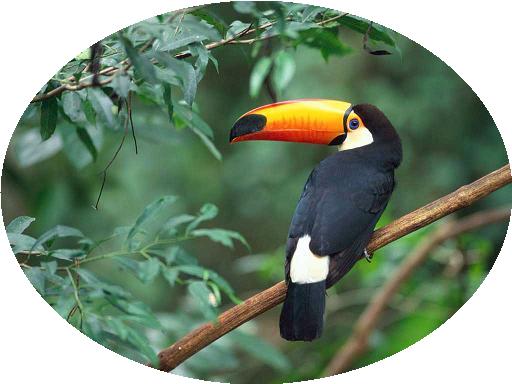
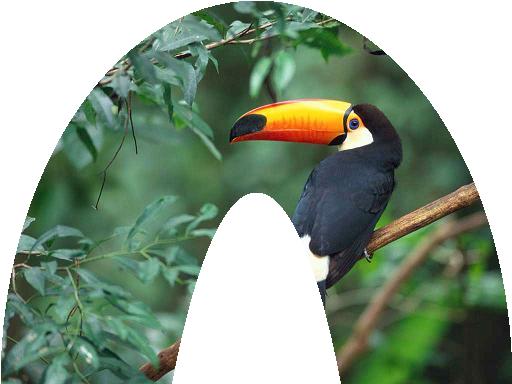
The samples below use the Graphics.SetClip function to draw shaped borders in your pictures.

The trick here is to use the CombineMode.Xor enumeration, that forces the drawing to the external part of the shape, like in the samples below.

We'll be playing with the source image below:


Prerequisites
Visual FoxPro 9 and the GdiplusX library from VFPX 


Sample 1: Ellipse Shape

DO LOCFILE("System.App") WITH _SCREEN.SYSTEM.Drawing * get an image file LOCAL loBmp AS xfcBitMap m.loBmp = .BITMAP.FromFile(GETPICT()) * create a gfx object that will allow us to make the transformation LOCAL loGfx AS xfcGraphics m.loGfx = .Graphics.FromImage(m.loBmp) LOCAL lnWidth, lnHeight m.lnWidth = m.loBmp.WIDTH m.lnHeight = m.loBmp.HEIGHT * create graphicsPath object. LOCAL loClipPath AS xfcGraphicsPath m.loClipPath = .Drawing2d.GraphicsPath.New() * an Ellipse shape m.loClipPath.AddEllipse(0, 0, m.lnWidth, m.lnHeight) * set Clipping region to Path. * CombineMode enumeration * http://msdn.microsoft.com/en-us/library/system.Drawing.Drawing2d.CombineMode.aspx * CombineMode.xor - two Clipping regions are combined by taking only the areas * enclosed by one or the other region, but not both. m.loGfx.SetClip(m.loClipPath, ; _SCREEN.SYSTEM.Drawing.Drawing2d.CombineMode.xor) * fill Rectangle to demonstrate Clipping region. m.loGfx.FillRectangle( .Brushes.White, 0, 0, m.loBmp.WIDTH, m.loBmp.HEIGHT) * save the image to the disk and show m.loBmp.SAVE("Clipped.jpg", "image/jpeg") RUN /N Explorer.EXE Clipped.jpg ENDWITH


Sample 2: Doughnut Shape


DO LOCFILE("System.App")
WITH _SCREEN.SYSTEM.Drawing
 * get an image file
 LOCAL loBmp AS xfcBitMap
 m.loBmp = .BITMAP.FromFile(GETPICT())
 * create a gfx object that will allow us to make the transformation
 LOCAL loGfx AS xfcGraphics
 m.loGfx = .Graphics.FromImage(m.loBmp)
 LOCAL lnWidth, lnHeight
 m.lnWidth  = m.loBmp.WIDTH
 m.lnHeight = m.loBmp.HEIGHT

 * create graphicsPath object.
 LOCAL loClipPath AS xfcGraphicsPath
 m.loClipPath = .Drawing2d.GraphicsPath.New()


 * a doughnut slice shape
 m.loClipPath.AddEllipse(0, 0, m.lnWidth, m.lnHeight * 2)
 m.loClipPath.AddEllipse(m.lnWidth / 4, m.lnHeight / 2, m.lnWidth / 2, m.lnHeight * 4)


 * set Clipping region to Path.
 * CombineMode enumeration
 * http://msdn.microsoft.com/en-us/library/system.Drawing.Drawing2d.CombineMode.aspx
 * CombineMode.xor - two Clipping regions are combined by taking only the areas 
 * enclosed by one or the other region, but not both. 
 m.loGfx.SetClip(m.loClipPath, ;
    _SCREEN.SYSTEM.Drawing.Drawing2d.CombineMode.xor)
 * fill Rectangle to demonstrate Clipping region.
 m.loGfx.FillRectangle( .Brushes.White, 0, 0, m.loBmp.WIDTH, m.loBmp.HEIGHT)
 * save the image to the disk and show
 m.loBmp.SAVE("Clipped.jpg", "image/jpeg")
 RUN /N Explorer.EXE Clipped.jpg
ENDWITH


Sample 3: Star Shape


DO LOCFILE("System.App")
WITH _SCREEN.SYSTEM.Drawing
 * get an image file
 LOCAL loBmp AS xfcBitMap
 m.loBmp = .BITMAP.FromFile(GETPICT())
 * create a gfx object that will allow us to make the transformation
 LOCAL loGfx AS xfcGraphics
 m.loGfx = .Graphics.FromImage(m.loBmp)
 LOCAL lnWidth, lnHeight
 m.lnWidth  = m.loBmp.WIDTH
 m.lnHeight = m.loBmp.HEIGHT

 * create graphicsPath object.
 LOCAL loClipPath AS xfcGraphicsPath
 m.loClipPath = .Drawing2d.GraphicsPath.New()


 * source for the star Drawing
 * http://www.java2s.com/code/vb/2d/graphicsPathdrawwithfillmodewinding.htm
 LOCAL lnRadius, lnpi, lnRadian72, N, lnEdges
 m.lnRadius  = m.lnHeight / 2
 m.lnpi   = 3.141592
 m.lnEdges  = 5
 m.lnRadian72 = (m.lnpi * 4.0 ) / m.lnEdges
 LOCAL laPoints(lnEdges)
 FOR m.N = 1 TO m.lnEdges
  m.laPoints(m.N) = .Point.New( ;
     + m.lnRadius * SIN( m.N * m.lnRadian72 ) + m.lnRadius, ;
     - m.lnRadius * COS( m.N * m.lnRadian72 ) + m.lnRadius )
 ENDFOR
 m.loClipPath.AddPolygon(@m.laPoints)
 * set the Clip mode to winding
 * Clipmode enumeration
 *http://msdn.microsoft.com/en-us/library/system.Drawing.Drawing2d.Fillmode.aspx
 m.loClipPath.Fillmode = _SCREEN.SYSTEM.Drawing.Drawing2d.Fillmode.winding

 * set Clipping region to Path.
 * CombineMode enumeration
 * http://msdn.microsoft.com/en-us/library/system.Drawing.Drawing2d.CombineMode.aspx
 * CombineMode.xor - two Clipping regions are combined by taking only the areas 
 * enclosed by one or the other region, but not both. 
 m.loGfx.SetClip(m.loClipPath, ;
    _SCREEN.SYSTEM.Drawing.Drawing2d.CombineMode.xor)
 * fill Rectangle to demonstrate Clipping region.
 m.loGfx.FillRectangle( .Brushes.White, 0, 0, m.loBmp.WIDTH, m.loBmp.HEIGHT)
 * save the image to the disk and show
 m.loBmp.SAVE("Clipped.jpg", "image/jpeg")
 RUN /N Explorer.EXE Clipped.jpg
ENDWITH


Notice that the only difference between the code samples is the shape definition !